[video width="640" height="360" m4v="http://www.nickwallace.us/blog/wp-content/uploads/2017/10/IMG_0139.m4v"][/video]
Our intro to fab assignment this week was to mount a motor, and after realizing that I could essentially buy a DC motor that pumps water (a peristaltic pump) I decided to make a physical interface for my pcomp project. Basically, make a device with a control panel that rains water onto an analog sensor, which feeds into p5 and creates rain within the sketch based on the amount of water you control.
This turned out to be more challenging from the design side than I initially anticipated, and during my office hours with Tom on Monday I had a few aha moments with regards to the whole process. At the end of the day, my current design is fundamentally flawed in that it isn't possible to accurately gauge the rate of water flow to draw rain in p5, and because the sensor doesn't magically dry out when you stop the "rain" from the control panel.
Although I wasn't able to get this quite to the level of completion that I wanted in 1 week, I'm fairly pleased with the results as a starting point. If nothing else, I learned a lot on both the physical and computing sides.
I plan to update this post a bit more this week when it's not 3:30am.
I went through a few panel designs before settling on a 2 button, 1 knob finish (bottom right):

Test fitting:

Final template cut in acrylic and sharpie-ed. This worked OK, but I definitely think it's best to use paint in the future:

I drilled a couple of holes in the box to run cables in/out:

Wired up a tiny pushbutton switch to hide under the box for an easter egg:

I cut a small block of plywood to act as a backstop for the breadboard, serving two purposes: keeping the breadboard in place and insuring the usb plug remains in the same place. Forgot to take a photo of the usb hole cut, but I did that freehand with a dremel:

With the box finished (minus wiring), I started to build the frame for the physical rain device. I glued + screwed some plywood I ripped on the panel saw to form the base:

While that was drying, I used a film canister from the junk shelf to cover the motor. This was sealed with hot glue:


I used a small piece of scrap plywood to create a raised motor mount:

I mounted this to the frame with two wood screws. Also pictured are the counter balance boards I mounted to the back of the frame with wood screws:

Testing the motor functionality with a bench power supply:
[video width="272" height="480" m4v="http://www.nickwallace.us/blog/wp-content/uploads/2017/10/IMG_0129.m4v"][/video]
To attach the wires to the back of the frame I went with the copious amounts of hot glue method. I connected the (+) rail of the motor to a DC barrel jack:

I drilled a hole for the raindrop sensor in the middle of the frame and glued the crap out of it as well:

Testing the functionality:
[video width="272" height="480" m4v="http://www.nickwallace.us/blog/wp-content/uploads/2017/10/testing_rainflow.m4v"][/video]
Unfortunately, I ran out of time to do much more. I originally planned to laser cut a "front" panel for the frame that had engraved clouds, cut out rain lines, and engraved grass/trees. Hopefully I'll have time to work on this more after the midterm.
[video width="640" height="360" m4v="http://www.nickwallace.us/blog/wp-content/uploads/2017/10/IMG_0139.m4v"][/video]
[video width="352" height="288" m4v="http://www.nickwallace.us/blog/wp-content/uploads/2017/10/IMG_0144.m4v"][/video]
Arduino code:
// define i/o pins
#define WATER_PUMP  3
#define PUMP_POT A6
#define RAIN_SENSOR A7
#define RAIN_BUTTON 8
#define THUNDER_BUTTON 10
#define EE_BUTTON 9

// define global vars
int lastRainState = 0;
boolean raining = false;
boolean thunderPress = false;
boolean eePress = false;
int potVal = 0;

void setup() {
  // setup i/o pins
  pinMode(WATER_PUMP, OUTPUT);
  pinMode(RAIN_SENSOR, INPUT);
  pinMode(RAIN_BUTTON, INPUT);
  pinMode(THUNDER_BUTTON, INPUT);
  pinMode(EE_BUTTON, INPUT);

  analogWrite(WATER_PUMP, 0);

  // turn on serial
  Serial.begin(9600);
  while (!Serial) {
  }
}

void loop() {
  // call thunder and easter egg functions
  thunder();
  ee();

  // toggle rainState on/off
  int rainState = digitalRead(RAIN_BUTTON);
  if (rainState == HIGH && lastRainState == LOW) {
    raining = !raining;

    if (raining) {
      // read pot value and remap
      potVal = analogRead(PUMP_POT);
      potVal = map(potVal, 0, 1023, 150, 255);

      // write to motor
      analogWrite(WATER_PUMP, potVal);
    } else {
      // motor is off
      analogWrite(WATER_PUMP, 0);
    }
  }
  lastRainState = rainState;

  if (raining) {
    // read pot value and remap
    int potVal = analogRead(PUMP_POT);
    potVal = map(potVal, 0, 1023, 150, 255);

    // write to motor
    analogWrite(WATER_PUMP, potVal);
  }

  // print rain sensor values
  int rainValue = analogRead(RAIN_SENSOR);
  rainValue = map(rainValue, 0, 1023, 50, 0); // map sensor pot val on 0-50 scale
  Serial.print(rainValue);

  if (thunderPress) { // print true if thunder button is pressed
    Serial.print(",");
    Serial.print("1");
    Serial.println();
    thunderPress = false;
    delay(5);
  } else if (eePress) { // print true if ee button is pressed
    Serial.print(",");
    Serial.print("2");
    Serial.println();
    eePress = false;
    delay(5);
  } else {  // otherwise just end the line
    Serial.println();
  }

  delay(50);
}

void thunder() {
  int thunderState = digitalRead(THUNDER_BUTTON);

  if (thunderState == HIGH) {
    thunderPress = true;
  }
}

void ee() {
  int eeState = digitalRead(EE_BUTTON);
  int lastEeState = 0;

  if (eeState != lastEeState) {
    if (eeState == HIGH) {
      eePress = true;
    }
  }
  lastEeState = eeState;
}
P5 code:
// drop.js code adapted from Dan Shiffman's purple rain coding challenge
// https://youtu.be/KkyIDI6rQJI

// define global vars
var drops = [];
var serial;
var portName = '/dev/cu.wchusbserial1410';

var inputData;
var sensorData = 0;
var otherPlay = 0;
var rainData = 0;

var rainSound;
var thunderSound;
var eeSound;

// preload SFX before setup
function preload(){
  rainSound = loadSound('rain.mp3');
  thunderSound = loadSound('thunder.mp3');
  eeSound = loadSound('rainmaker.mp3');
}

function setup() {
  createCanvas(640, 360);
  for (var i = 0; i < 1000; i++) { drops[i] = new Drop(); } rainSound.play(); // setup serial connection for analog sensor input serial = new p5.SerialPort();
serial.on('connected', serverConnected);
serial.on('open', portOpen);
serial.on('data', serialEvent);
serial.list(); serial.open(portName); }

function serverConnected() { }
function portOpen() { }

function serialEvent() {
inputData = serial.readLine(); // check that the array has at least 1 element if (inputData.length > 0) {

    var sensorReadings = inputData.split(',');

    sensorData = int(sensorReadings[0]);
    otherPlay = int(sensorReadings[1]);
  }
}

function draw() {
  background(220,220,220);

  // play thunder sound when button is pressed
  if (otherPlay == 1) {
    thunderSound.play();
    otherPlay = 0;
  } else if (otherPlay == 2) { // play matchbox 20 clip when button is pressed
    eeSound.play();
    eeSound.setVolume(.4);
    otherPlay = 0;
  }

  // smooth sensor data using linear interpolation and show as %
  rainData = lerp(rainData, sensorData, 0.04);
  text('rain percentage: ' + round((rainData /50)*100) + '%', 30, 30);

  // show rain on screen
  var rainAmount = rainData * 15;
  for (var i = 0; i < rainAmount; i++) {
    drops[i].fall();
    drops[i].show();
  }

  // set rain sound vol based on sensor input
  var rainVol = rainData * 2
  var volume = map(rainVol, 0, 50, 0, 1);
  rainSound.setVolume(volume);
}


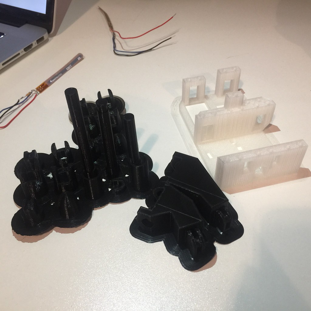
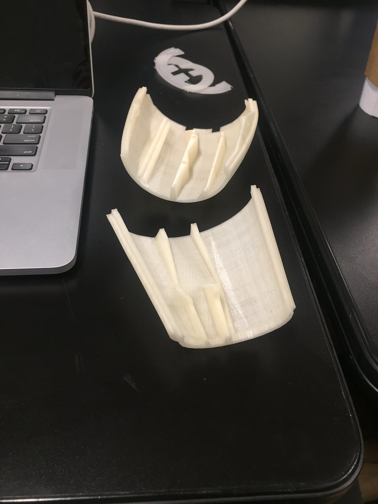
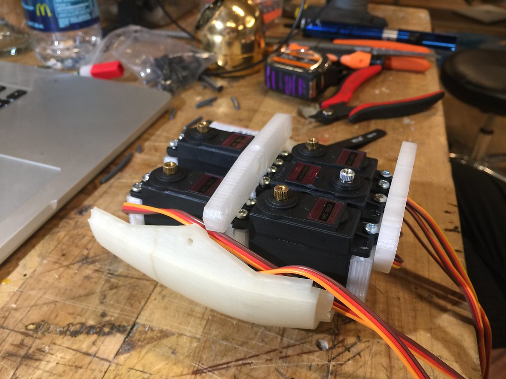
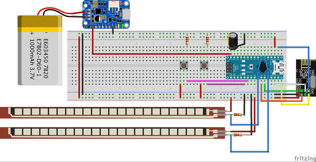
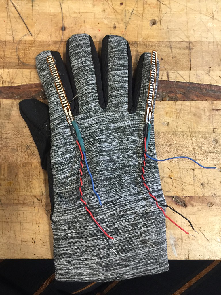
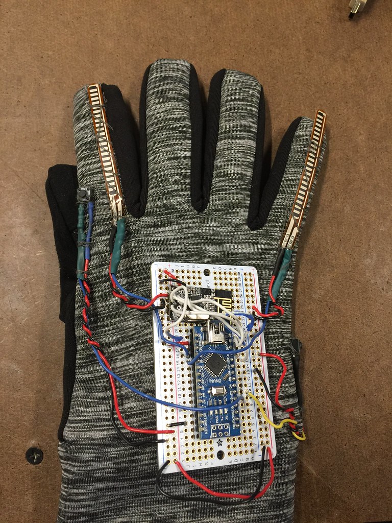
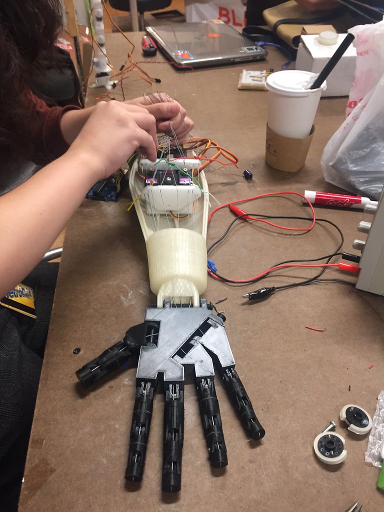
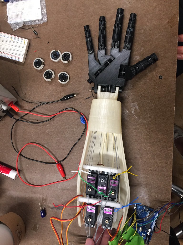
 For the midterm, Tong Wu and I built an interactive installation that lets a person play “Rock, Paper, Scissors” against a robotic hand by wearing a glove outfitted with flex sensors.
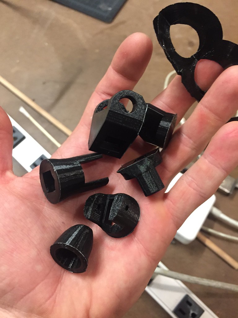


 I've been toying with the idea of using a Pi Zero to build a wireless music streaming box for a while. My original plan was to use cherry wood and metal to give the box a Hi-Fi look, but the wood I ordered from Rockler ended up getting delayed, and isn't coming until this Friday (10/6).


 Before coming to ITP, I had never used Adobe Illustrator (Ai) or a laser cutter. I'm very happy that has changed.


 In his book "The Art of Interactive Design", Chris Crawford defines interaction as "a cyclic process in which two actors alternately listen, think, and speak." He goes on to apply this definition metaphorically to a variety of different objects and processes to argue that interactivity falls on a scale; it is not simply binary. Ultimately, he argues that many processes are responsive without being truly interactive (refrigerators, reading, etcetera).


